English
- English
- Español
- Português
- русский
- Français
- 日本語
- Deutsch
- tiếng Việt
- Italiano
- Nederlands
- ภาษาไทย
- Polski
- 한국어
- Svenska
- magyar
- Malay
- বাংলা ভাষার
- Dansk
- Suomi
- हिन्दी
- Pilipino
- Türkçe
- Gaeilge
- العربية
- Indonesia
- Norsk
- تمل
- český
- ελληνικά
- український
- Javanese
- فارسی
- தமிழ்
- తెలుగు
- नेपाली
- Burmese
- български
- ລາວ
- Latine
- Қазақша
- Euskal
- Azərbaycan
- Slovenský jazyk
- Македонски
- Lietuvos
- Eesti Keel
- Română
- Slovenski
- मराठी
- Srpski језик
China High-quality Socket Joint Manufacturer
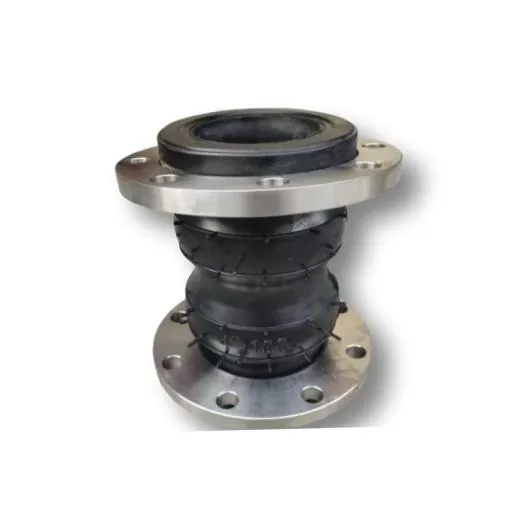
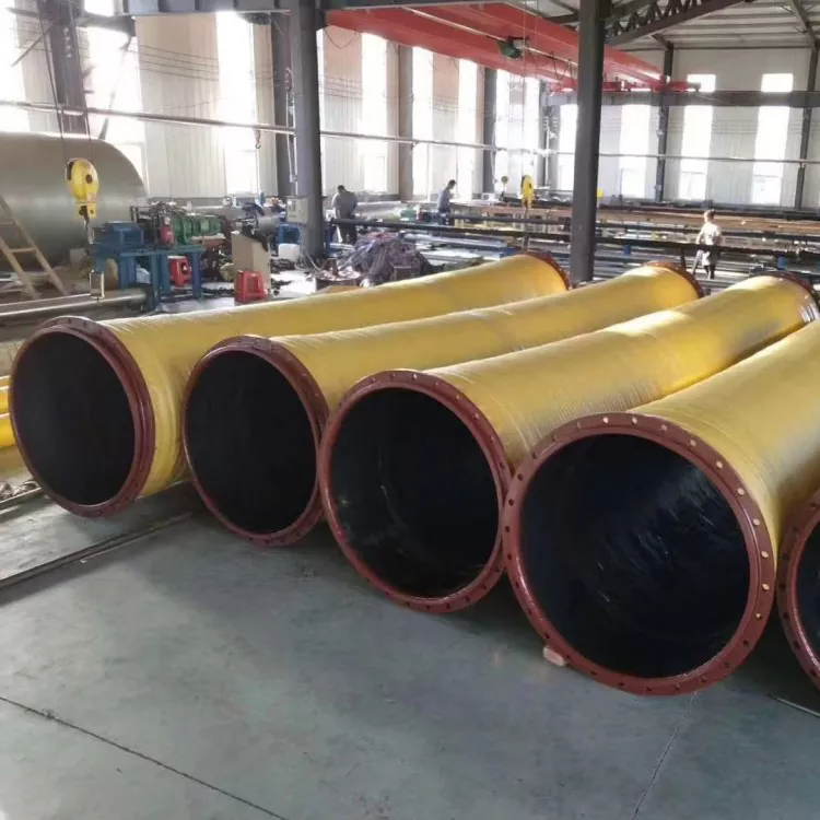
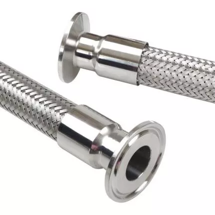
Socket Joint is a fundamental component in modern piping systems and structural assemblies, engineered to provide a reliable, flexible connection between two sections of pipe, tube, or structural elements. Unlike rigid flange or welded joints, a socket joint accommodates a degree of axial movement and angular deflection, which is critical in environments subject to thermal expansion, ground settlement, or dynamic loading.
FAQ
Q: What is the fundamental difference between a push-on and a restrained?
A: A push-on socket joint relies solely on the compressed elastomeric gasket to generate a watertight seal, but it does not prevent the spigot from pulling out under axial thrust. External thrust blocks or passive soil restraint at bends and tees are mandatory. A restrained socket joint, by contrast, incorporates a positive mechanical lock—such as a locking segment, grip ring, or welded bead—that transfers axial tensile forces through the joint itself into the pipe wall. This makes the pipeline self-anchoring, allowing it to resist thrust without concrete reaction blocks. Restrained joints are more expensive but essential for steep slopes, aerial crossings, and seismically active areas.
Q: How do you calculate the maximum allowable angular deflection for a socket joint in a curved alignment?
A: You divide the total angle change required by the deflection rating per joint (provided by the manufacturer, typically 1.5° to 5°) to determine the minimum number of joints needed in the curve. For example, a 12° horizontal bend in DN 300 pipe using joints rated for 3° each requires at least four joints with 3° of offset each. However, practical installation mandates reducing the per-joint deflection to 75% of the rated maximum to avoid edge loading on the gasket lip; for that 12° bend, you would actually use six joints at 2° each. Always consult the manufacturer’s curvature radius tables, and never exceed the recommended unsupported length behind the joint.
Q: What gasket material does JIDONGDA recommend for a water treatment plant using 5% ferric chloride solution at 40°C?
A: For this environment, we recommend an EPDM gasket with a peroxide cure system rather than sulfur cure, because ferric chloride is a strong oxidizing agent. Standard sulfur-cured EPDM may suffer chain scission. Alternatively, for maximum chemical resistance, a fluoroelastomer (FKM) gasket can be supplied under our JD-FKM-75 specification, rated for continuous contact with pH 2–12 solutions up to 150°C. It is critical to verify the gasket’s volume swell after 72-hour immersion in the specific chemical at service temperature; our internal limit is 8% maximum swell for dynamic joints.
Q: Can it be used for above-ground piping, and what support spacing is required?
A: Yes, they are fully suitable for above-ground installations, especially in pump stations and water treatment facilities. The support spacing must comply with the pipe material’s span tables, considering the additional mass of the socket and restrained mechanism. For DN 200 ductile iron pipe, typical support spacing is 4.0 meters for single-span configuration. Crucially, install a fixed support within one pipe diameter of the socket joint to prevent the joint from acting as a hinge and experiencing repeated angular movement from thermal cycling. For PN16 restrained joints, longitudinal expansion must be absorbed by an expansion joint placed at least 20 joint lengths away.
Q: What pressure test procedure ensures a socket joint installation is leak-free?
A: After the pipeline backfill and minimum curing of thrust blocks (if any), hydrostatic testing should proceed in segments. Fill and bleed all air through high-point vents. Pressurize to the system test pressure—typically 1.5 times the working pressure—in increments of 2 bar, holding each stage for 5 minutes to allow gasket relaxation. Once at full test pressure, maintain it for at least 2 hours while measuring the volume of makeup water required to sustain pressure. Acceptance criteria per AWWA C600 allow makeup water not exceeding 0.00045 gallons per inch of diameter per mile of pipe per 24 hours. For a DN 500, 500-meter test section, the allowable makeup is extremely low, on the order of a few liters. A rapid pressure drop usually indicates joint separation, spigot not fully inserted, or a gasket rolled during assembly.
Q: How does surface preparation of the spigot affect the performance of a socket joint during assembly?
A: Proper spigot preparation is the single most important step. The insertion depth mark must be measured from the spigot end and clearly painted or taped. The spigot surface should be wiped clean of dirt, ice, or moisture. Apply the manufacturer-supplied lubricant (petroleum-free for EPDM gaskets) in a thin, even coat around the spigot nose and 50 mm behind the mark. Do not use hydrocarbon-based grease, which can soften the rubber and cause a blowout. The spigot must be centered in the socket using a crowbar or hydraulic pusher, and inserted in a single, steady motion without hesitation; stopping mid-assembly can dislodge the gasket from its seat and result in a delayed leak.
Q: What are the typical installation tolerances for a socket joint in a trench?
A: The long axis of the socket and spigot should be aligned within 2° before insertion—this is verified by sighting along the pipe. The socket gap (the distance between the spigot insertion mark and the socket face after assembly) must be uniform around the circumference within ±3 mm. For restrained socket joints, hydraulic jacks should be used to pull the joint home completely against the lock ring; any residual gap can reduce the allowable axial load capacity by 40%.


- View as

45° Socket Weld Elbow
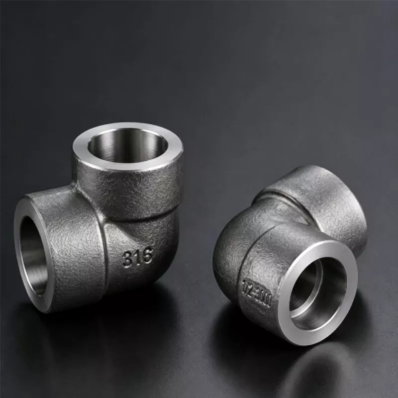
The JIDONGDA factory’s 45° Socket Weld Elbow is a precision-engineered forged piping component designed for controlled flow direction change in high-pressure small-bore pipeline systems. Unlike sharp-angle fittings, it provides a smoother 45-degree transition that helps reduce turbulence, stabilize internal pressure, and improve overall flow efficiency. Manufactured with a permanent socket weld structure, it ensures long-term sealing reliability and structural integrity in demanding industrial environments such as oil & gas, chemical processing, power generation, and instrumentation piping systems. This makes it a preferred solution for engineers and procurement teams seeking both hydraulic performance optimization and welded connection durability.

90° Socket Weld Elbow
Why settle for middlemen when you can partner with an industrial titan? JIDONGDA is an established supplier with a sprawling manufacturing facility, offering versatile 90° Socket Weld Elbow at wholesale price. Contact our international office right now for premium VIP service!
JIDONGDA offers premium Socket Joint manufactured under strict quality standards with reliable delivery and competitive factory pricing. Contact us for more details.